Unbricking Arduino Portenta
Reconfiguring the PMIC registers to get Portenta running again

I am a full stack developer and a Machine Learning enthusiast.
I had been working with an Arduino Portenta board on a Machine Learning project at my college. The firmware was written, the Machine Learning model was trained and flashed into Portenta, my PCB prototype was ready as well. However, things took a different turn when the Arduino Portenta board got bricked, giving me the chance to solve a new problem. It took me over 2 weeks to fix this issue but by following the below steps it can be fixed in less two hours given any hardware, connection troubleshooting.
What does bricking mean?
In Arduino Portenta, while using Mbed OS, if an incorrect power configuration is detected then the PMIC registers are cleared so that there is no power supply to the STM32 chip on the board, making the board useless. However, it is worth noting that many experienced people have faced this problem without making any errors in the power supply configuration and there have been many helps asked on forums about the same. The charging status LED, i.e. orange light glowing is a good indication of the board being bricked. Also if one checks by probing a multimeter on the 3.3V and 5V pins, one might not get any voltage. Though a protection feature, the problem of board bricking can be a really cumbersome one.
Fixing a bricked board
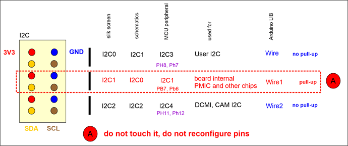
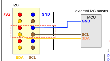
Fixing a bricked board is not a straightforward task as the STM32 chip will neither get power nor will be detected by the laptop. Hence, we cannot write the correct configuration of the PMIC registers using I2C protocol on Portenta. However, if one takes a close look at schematics, the PMIC interacts with the STM32 chip using I2C1 interface. So, if we connect to the I2C1 interface with another device like Raspberry Pi or Arduino, we can programmatically reconfigure the PMIC registers.
I first took a working Portenta board and read the PMIC registers using I2C1 interface and Raspberry Pi using the script. I got the correct PMIC configuration.
import smbus2

def read_all_registers(i2c_address, register_count):
    bus = smbus2.SMBus(1)
    register_values = []

    for register in range(register_count):
        try:
            value = bus.read_byte_data(i2c_address, register)
            register_values.append((register, value))
        except Exception as e:
            print(f"Error reading register {register}: {e}")

    bus.close()
    return register_values
I was able to retrieve the correct PMIC configuration using the above function. The parameters are mentioned in the datasheet. The connections have been made by a lot of embedded systems enthusiasts who encountered the same problem, but the register values are not fixed. They can vary from board to board endorsing the necessity of this step.
import smbus2
import time

def read_i2c(dev_addr, m, n):
    print()
    for i in range(m):
        print(f"{i*16:02X} | ", end="")
        for j in range(n):
            with smbus2.SMBus(1) as bus:
                n_written = bus.write_byte(dev_addr, i*16 + j)
                n_read = bus.read_byte(dev_addr)
                print(f"{n_read:02X} ", end="")
        print()

def write_i2c(dev_addr, reg_addr, reg_val, n):
    print()
    for i in range(n):
        with smbus2.SMBus(1) as bus:
            n_written = bus.write_byte_data(dev_addr, reg_addr[i], reg_val[i])
            n_read = bus.read_byte_data(dev_addr, reg_addr[i])
            print(f"Wrote {n_written} bytes to register {reg_addr[i]:02X}: wrote {reg_val[i]:02X}, read {n_read:02X}")

def scan_i2c():
    print()
    print("I2C Scanner")
    print("Scanning...")
    devices = 0
    for address in range(1, 127):
        try:
            with smbus2.SMBus(1) as bus:
                bus.read_byte(address)
                print(f"I2C device found at address 0x{address:02X} !")
                devices += 1
        except Exception as e:
            pass

    if devices == 0:
        print("No I2C devices found")
    else:
        print("done")

if __name__ == "__main__":
    reg_addr = list(range(160))
    reg_val = [
        0x7C, 0x00, 0x11, 0x00, 0x00, 0x00, 0x88, 0x00, 0x00, 0x07, 0x00, 0x04, 0x07, 0x04, 0x00, 0x03,
        0x00, 0x00, 0x00, 0x00, 0x00, 0x00, 0x00, 0x00, 0x00, 0x07, 0x00, 0x00, 0x00, 0x00, 0x00, 0x00,
        #other values
    ]

    dev_addr = 0x08

    read_i2c(dev_addr, 16, 16)
    write_i2c(dev_addr, reg_addr, reg_val, 160)
    read_i2c(dev_addr, 16, 16)
    scan_i2c()
What if the bootloader is corrupted?
For me, the above steps were enough as my bootloader was not corrupted so I have not verified the steps of fixing the bootloader. If the above steps have been completed, one can one can fix the bootloader by flashing the bootloader again using an STM32 ST-Link (SWD) debugger by making the following connections and using the STM32CubePrograammer software.
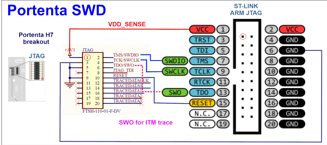
One can try reading the Flash ROM first 0x08000000 (the location of the bootloader, up to 0x0803FFFF, afterwards your user FW/sketch follows). If able to read the Flash ROM, find your appropriate bootloader.bin file and flash it starting from the address 0x08000000. It is expected that a fading glowing green light will show up on the board and the charging orange LED will not be seen glowing.
After unbricking the board, one can reflash firmware using the regular IDE.


